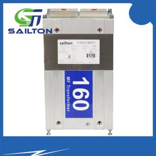
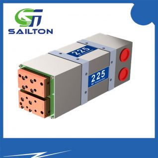
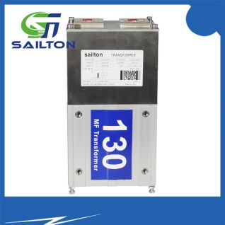
Products
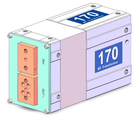
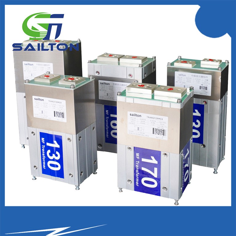
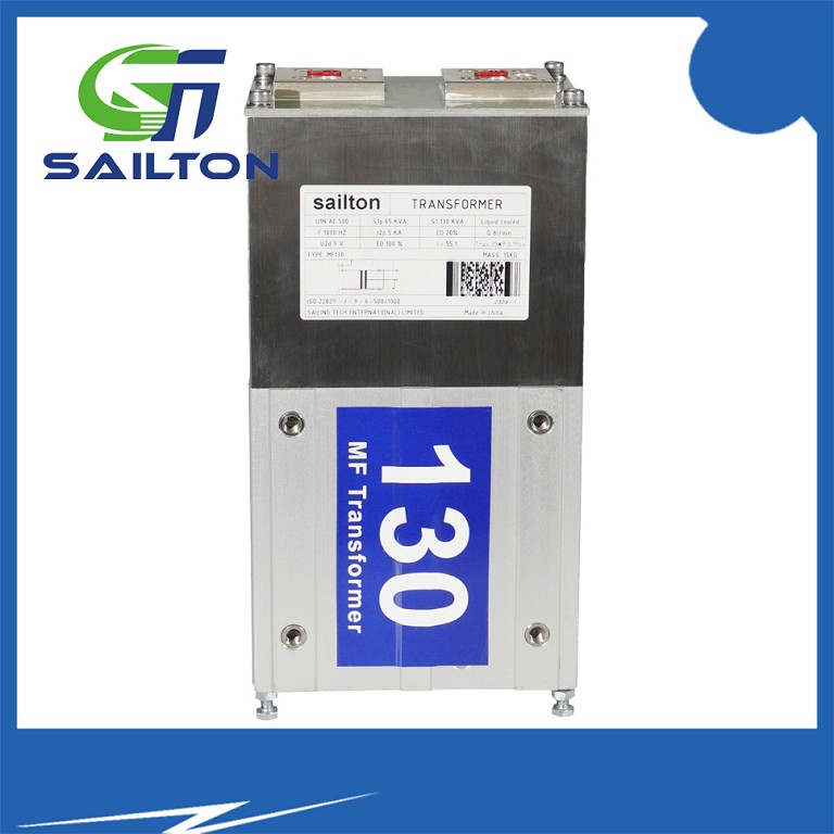
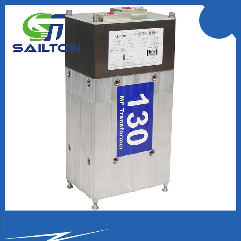
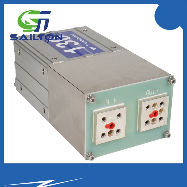
SAILTON MF Resistance Spot welder transformers Resistance Welding Machine Parts
For all kinds of intermediate frequency, power frequency resistance welding machine.
Such as automobile welding clamp,seam welding machine, mesh welding machine and so on.
Inverter Welding Transformer
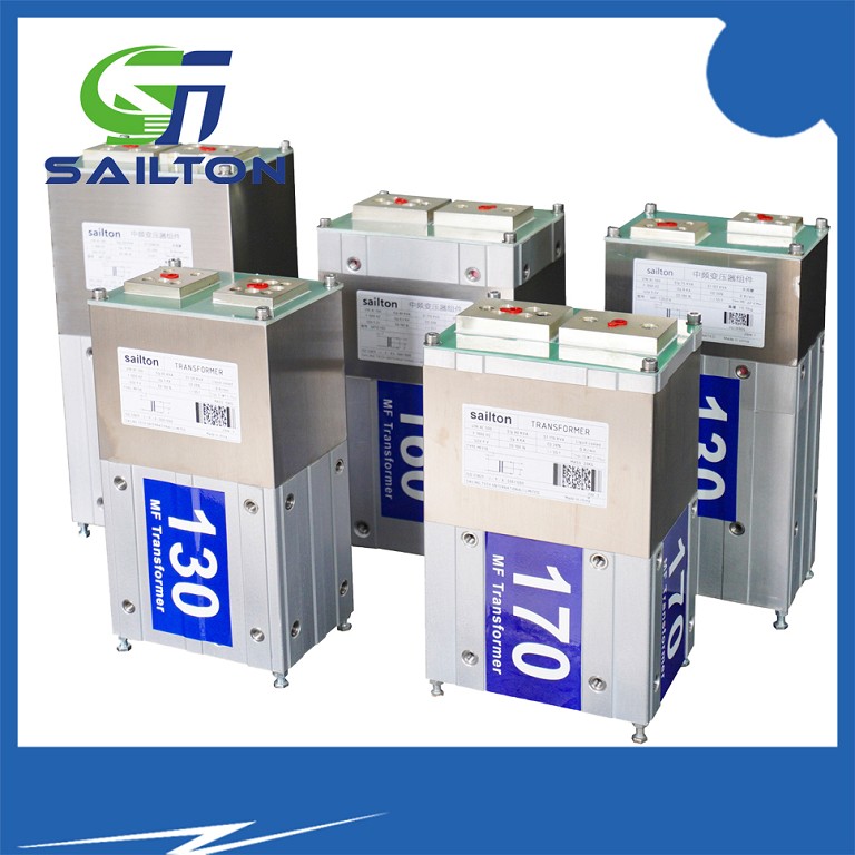
Application
1) Spot Welder 2) SEAM Welder 3) Projection Welder 4) High Frequency Induction Heating
For all kinds of intermediate frequency, power frequency
resistance welding machine.Such as automobile welding clamp,
seam welding machine, mesh welding machine and so on.
Brief introduction
Medium-frequency (MF) transformers are a result of recent advances in resistance welding technology.
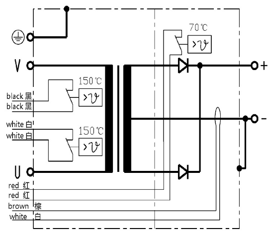
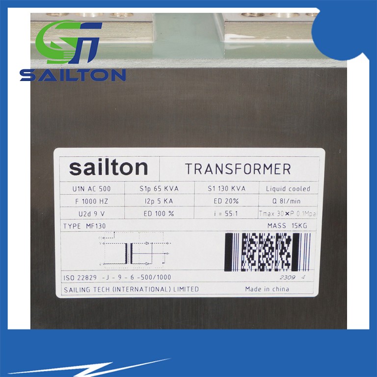
They are powered by a transistor inverter, supplying square wave AC 500 V @ 1000 Hz which is converted
by the MF transformer to a low voltage high current AC. This low voltage AC current is rectified to DC by
a diode block built into the transformer.The higher operating frequency of an MF system allows efficient
energy conversion using a smaller and lighter transformer.Other benefits with MF transformers used in
portable and robotic welding guns are:The reactance of the welding loop only limits the upslope and down
slope of the welding current, while the peak welding current in limited only by the welding loop’s resistance.
The net result is again smaller transformer, especially when welding with large throat, high-impedance guns.
MF welding is less demanding on the plant power system. The MF inverter draws balanced line current from
all 3 phases and operates at a high power factor (0.9).With MF transformers the peak welding current almost
equals its RMS value, which helps to obtain quality welds with no splash and constantstrength even at lower
pressure.The high frequency permits much faster – 1000 times per second - process control, which again results
in better weld quality.
Technology selection table
| 型号 / TYPE | Unit | MF6160 | MF170-3G | MF130 | MF170 | MF220 | MF225 | ||
|
初级额定电压 /primary nominal voltage |
v | 500 | 500 | 500 | 500 | 500 | 500 | ||
| 频率 / frequency | Hz | 1000 | 1000 | 1000 | 1000 | 1000 | 1000 | ||
| 负载持续率为 20%的标称功率/ nominal power at 20%ED | kVA | 170 | 170 | 130 | 170 | 220 | 350 | ||
| 负载持续率为 50%的标称功率/ nominal power at 50%ED |
kVA | 105 | 105 | 85 | 105 | 150 | 225 | ||
| 负载持续率为 100%的标称功率/ nominal power at 100%ED |
kVA | 75 | 75 | 58 | 75 | 117 | 170 | ||
| 空载电压/ secondary voltage | V | 9 | 9 | 9 | 9 | 13 | 13 | ||
|
持续直流电流 / permanent DC current 100% |
A | 8500 | 8500 | 6500 | 8500 | 9000 | 13000 | ||
| 短路电流/ short-circuit current | KA | 38 | 38 | 32 | 38 | 45 | 55 | ||
| 变压比 / turns ratio | N1/N2 | 55:1 | 55:1 | 55:1 | 55:1 | 38:1 | 38:1 | ||
| 重量 / weight | kg | 20 | 20 | 15 | 20 | 25 | 40 | ||
| 温度开关 / temperature switch | 2 x 150 °C, 1 x 70 °C 温度开关 (热保) /Temperature switch |
||||||||
| 绝缘等级 /insulation class | F(155°C) | ||||||||
| 测流线圈/ eddy current testing | 150mV/KA±3% | 150mV/KA±3% | 150mV/KA±3% | 150mV/KA ±3% | - | 150mV/KA±3% | |||
| 尺寸/ size | mm | 171.5×127×295 | 160*130*256 | 150*106*276+82 | 160X125X262 | 160×125×318 | 171.5*151*450 | ||
| 冷却水流量/ cooling water quant. Q Tmax. 30℃ | I/ min | 8 | 8 | 8 | 8 | 12 | 12 | ||
| 压差 / pressure drop p (Q=6l / min ) | Mpa | <0.2 | <0.2 | <0.2 | 160X125X262 | <0.1 | <0.1 | ||
| 注:电极输出方式可以按需要调整 内置()个整流管 | 2 | 2 | 2 | 2 | 4 | 4 | |||
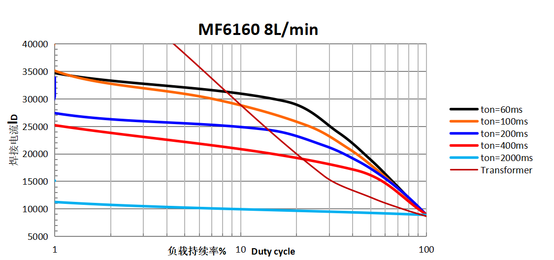
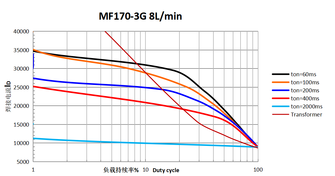
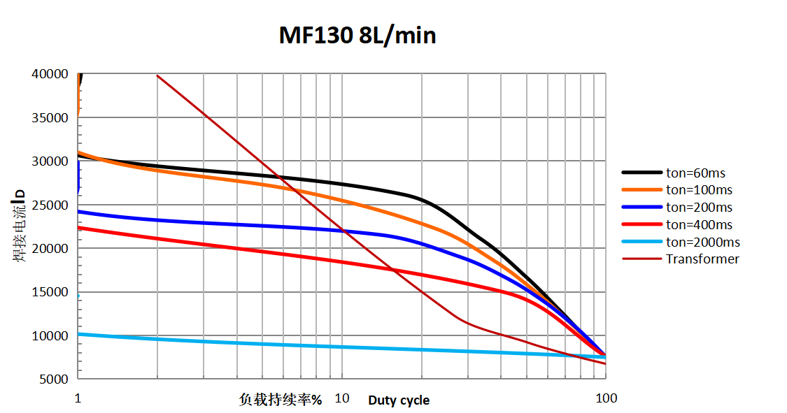
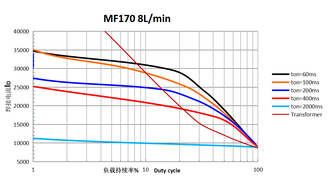
Load endurance chart
| Type | ||
| MF6160 |
负载曲线 Load diagram |
 |
|
|
||
| MF170-3G |
负载曲线 Load diagram |
 |
| MF130 |
负载曲线 Load diagram |
 |
|
|
||
| MF170 |
负载曲线 Load diagram |
 |
|
|
||
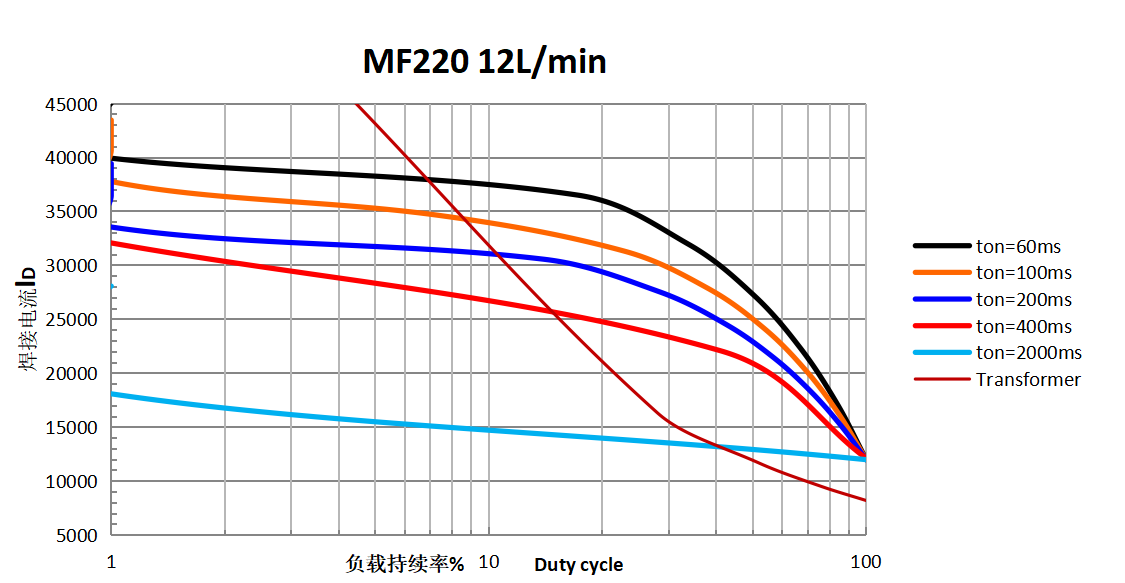
| MF220 |
负载曲线 Load diagram |
 |
|
|
||
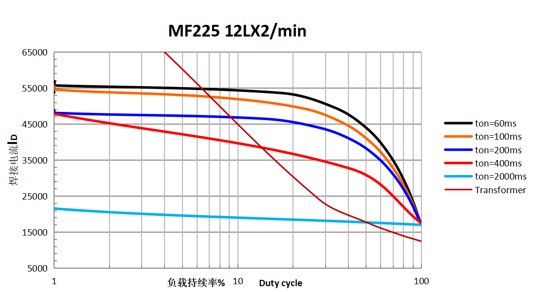
| MF225 |
负载曲线 Load diagram |
 |
|
|
注:
整流器额定值:负载持续率%基于从一次焊接开始到下一次焊接开始的最短时间
开机时间/(开机时间+关机时间)
变压器额定值:负载持续率%为一分钟内的总开机时间
NOTE:
If the secondary connection and secondary voltage need to be adjusted , please contact Manufacture
Duty factor diodes:from the beginning of one welding time to the beginning of the next welding (Spot to Spot)
Duty factor transformer:all welding time within 60s
